Some Known Incorrect Statements About Wedge Barriers
Fascination About Wedge Barriers
Table of ContentsHow Wedge Barriers can Save You Time, Stress, and Money.See This Report about Wedge Barriers

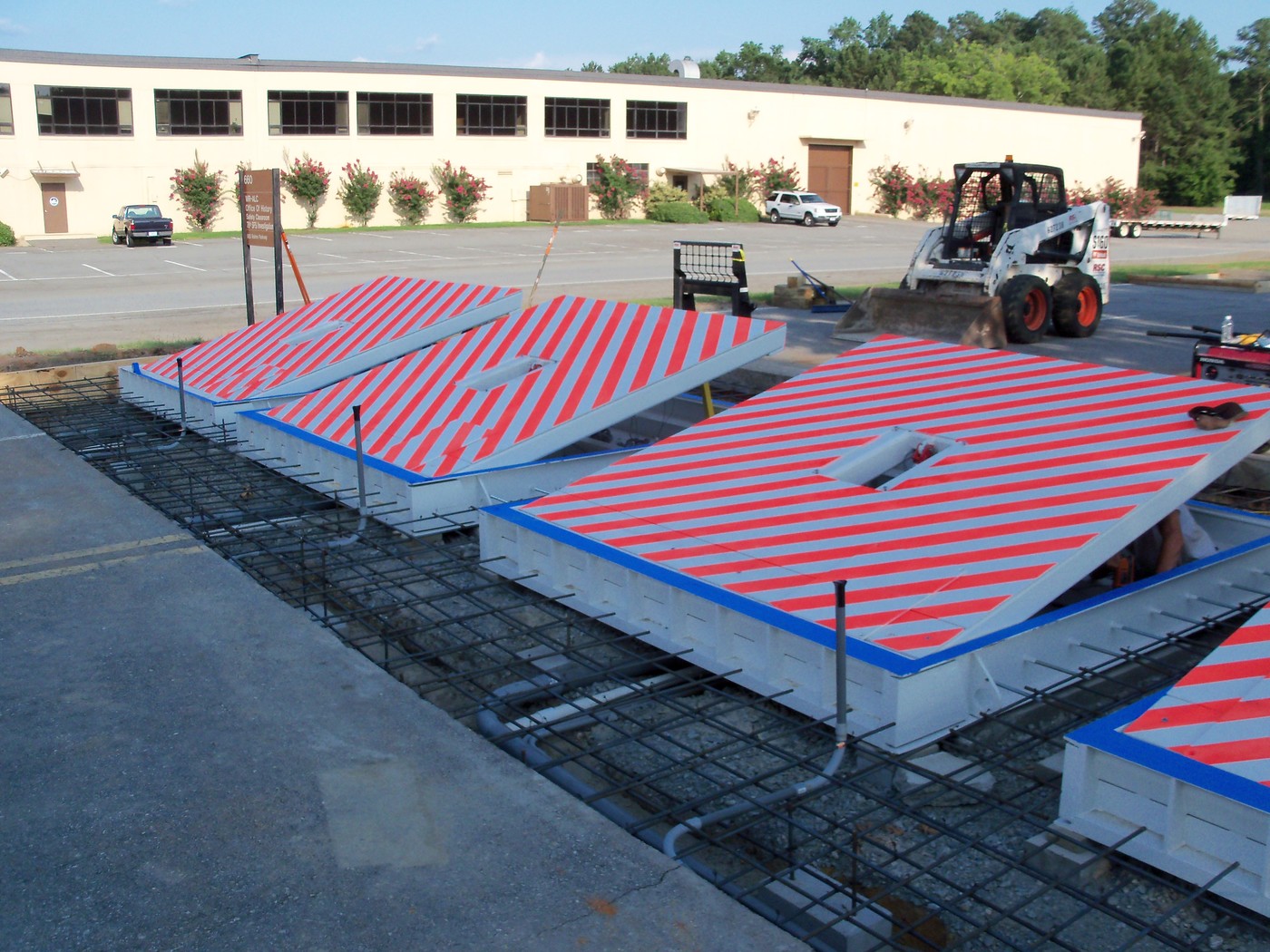
18 may be done faster, easily, and price effectively. FIG. In specific embodiments, the anchor 30 might be a steel framework including plates, beams(e. g., I-beams ), and/or various other frameworks that are secured within the structure 14, which may be concrete. At the surface area 12, an upper side 28 of the support 30 might be at least partly subjected
, therefore enabling the add-on of the barrier 10 to the anchor 30. g., threaded holes)in several light beams or plates of the support 30 may be subjected to the surface 12. In this fashion, bolts 32 or various other mechanical bolts may be utilized to protect the obstacle 10 to the anchor 30. As the barrier 10 is placed to the surface area 12 of the foundation 14, collection of particles and other product underneath the barrier might be decreased, and parts of the bather 10 might not be revealed to below quality settings. As shown by referral character 52, the training mechanism 50 includes components disposed beneath the wedge plate 16. The elements 52 below the wedge plate 16 may include an electromechanical actuator, a webcam, one or more cam surfaces, and so forth. Additionally, the training mechanism 50 includes a spring setting up 54
The springtime rod 58 is coupled to a webcam(e. g., web cam 80 displayed in FIG. 4) of the lifting mechanism 50. The springs 60 disposed regarding the springtime rod 58 are kept in compression by spring supports 62, consisting of a taken care of springtime support 64. That is, the fixed spring assistance 64 is fixed family member to the structure 14 et cetera of the bather 10.
Some Known Details About Wedge Barriers
The remaining pressure applied to
the cam webcam deploy the wedge plate 16 may might provided supplied an electromechanical actuator 84 or other various other. The spring setting up 54 and the actuator 84(e. Wedge Barriers. g., electromechanical actuator)may run with each other to convert the web cam and raise the wedge plate 16.
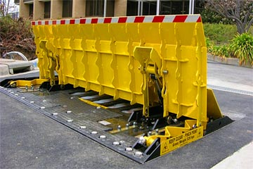
As mentioned over, the springtime assembly 54 applies a constant pressure on the web cam, while the electromechanical actuator might be controlled to exert a variable pressure on the camera, thus allowing the lifting and reducing( i. e., deploying and retracting )of the wedge plate 16. In specific embodiments, the consistent force applied by the spring assembly 54 may be flexible. g., electromechanical actuator) is impaired. As will be valued, the spring setting up 54 might be covered and secured from particles or various other components by a cover plate(e. see this here g., cover plate 68 revealed in FIG. 4) that might be substantially flush with the raised surface 38 of the structure 14. As pointed out above, in the released placement, the wedge plate 16 offers to block gain access to or travel past the barrier 10. As an example, the barrier 10(e. g., the wedge plate 16 )may block pedestrians or cars from accessing a property or pathway. As reviewed over, the obstacle 10 is connected to the support 30 safeguarded within the foundation 14,
front braces 71. As a result, the linkage settings up 72 might pivot and turn to make it possible for the collapse and extension of the linkage assemblies 72 during retraction and deployment of the bather 10. The link assemblies 72 cause activity of the wedge plate 16 to be limited. If a car is taking a trip in the direction of the deployed wedge plate 16(e. For instance, in one condition, the safety and security legs 86 might be expanded duringmaintenance of the barrier 10. When the safety legs 86 are deployed, the security legs 86 sustain the weight of the wedge plate 16 versus the surface 12. Consequently, the training mechanism 50 may be shut off, serviced, gotten rid of, replaced, etc. FIG. 5 is partial viewpoint view of an embodiment of the surface-mounted wedge-style barrier 10, illustrating the cam 80 and the camera surfaces 82 of the training mechanism 50. Especially, 2 webcam surface areas 82, which are referred to as lower camera surface areas 83, are positioned listed below the cam 80. The lower webcam surfaces 83 might be repaired to the surface 12 (e. For instance, the reduced webcam surfaces 83 and the mounting plate 85 might form a single piece that is protected to the anchor 30 by bolts or various other mechanical fasteners. Additionally, two webcam surface areas 82, which are read the full info here described as upper webcam surfaces 87, are positioned above the web cam 80 and paired to (e. In other personifications, stepping in layers or plates might be placed between the surface 12 and the reduced camera surface areas 83 and/or the wedge plate 16 and the top cam surfaces 87 As mentioned over, the web cam
80 converts along the webcam surfaces 82 when the wedge plate 16 is lifted from the retracted setting to the deployed position. In addition, as pointed out over, the springtime assembly 54 (see FIG. 3 )might supply a pressure acting on the webcam 80 in the direction 102 via spring pole 58, which might decrease the pressure the electromechanical actuator 84 is required to put on the web cam 80 in order learn the facts here now to activate and lift the wedge plate 16. 1 )to the released position(see FIG. 4). As revealed, the webcam 80 consists of track wheels 104(e. g., rollers), which get in touch with and translate along the web cam surface areas 82 throughout procedure.